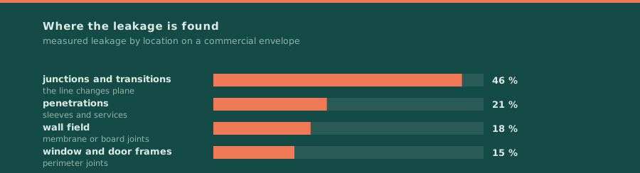
The airtightness line is the continuous boundary in a wall or roof assembly that stops air moving through it. It is not the same as the vapour line and it is usually not the same as the weather line, and most air leakage happens where the line changes plane.
Airtightness line: continuity is the whole specification
rev Cissue 04rev Crots yes — the figures above move with the standarddrawn by The Transom Set (a named set, not a person)
Three lines, three jobs
The weather line sheds bulk water. The air line stops air moving, which is what carries most of the moisture and most of the energy loss. The vapour line controls how much vapour diffuses through, which is a slow process compared with air movement. A wall where one material is expected to do all three jobs is a wall with a problem in it.
| Line | Job | Material | Where it usually is |
|---|---|---|---|
| weather | shed bulk water | cladding, membrane | outermost |
| air | stop air movement | membrane, board, sealant | mid-wall, on sheathing |
| vapour | limit diffusion | membrane, coating | warm side of the insulation |
| thermal | stop conduction | insulation | continuous layer |
The junctions are the specification
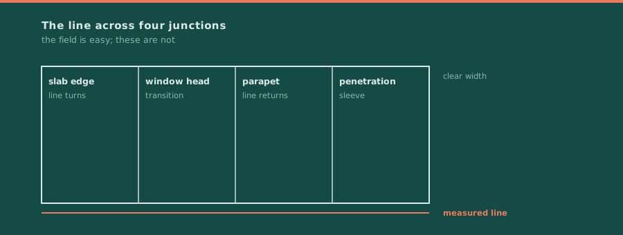
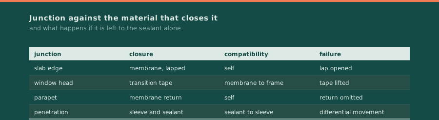
A membrane field is easy. What decides the measured figure is what happens where the membrane meets a window head, a parapet, a slab edge, a penetration or another membrane. Each of those is a change of plane, and each one needs either a transition material or a sealant that is compatible with both surfaces.
That is why the airtightness line is drawn as a single continuous line on the drawings before it is specified. A line that cannot be traced around the whole envelope without lifting the pen is a line that will leak, and the leak will be at the point where the line was ambiguous.
The airtightness line is not the same as the vapour line, and on a hot-humid site it is often not the same as the weather line either. Three lines, three positions, and a drawing that shows only one of them has not answered the question.
Where the definition stops
This page owns the air line. The operable joint in the window is owned by the weatherstrip page, the drainage path behind the cladding by the drainage page, and the measurement by the air leakage test. Nothing here is repeated there.
Documents this sheet is drawn from
- 1ASTM E2357-18 Standard Test Method for Determining Air Leakage Rate of Air Barrier Assembliessupports the air leakage test method for air barrier assemblies used here
- 2NISTIR 4821: Envelope Design Guidelines for Federal Office Buildings - Thermal Integrity and Airtightnesssupports the thermal integrity and airtightness guidance the line placement follows
- 3NIST Commercial Building Airtightness Databasesupports the measured commercial airtightness data the q50 figure is compared against
Each line points at one specific document, with its own title as the link text. No line is a home page and no line is a search result.
Sign the sheet and stop Sign the sheet and stop once you can trace the line around the whole envelope without lifting the pen. That is the test.